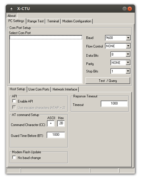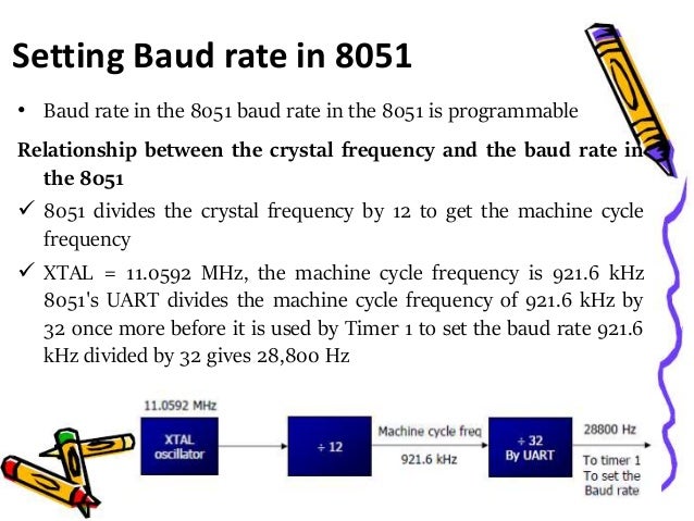
The stty utility sets or reports on terminal I/O characteristics for the device that is its standard input. These characteristics are used when establishing a connection over that particular medium. Cat doesn't know the baud rate as such, it rather prints on the screen information received from the particular connection. As an example stty -F /dev/ttyACM0 gives the current baud rate for the. NOTE: Docklight tries to align the baud rate / bit timing results to a standard serial baud rates like 115200. But by design and due to usual tolerances of the baud rate generator in serial devices, there can be deviations and unusual/nonstandard values can appear. A +/- 3% tolerance window is usually within specs and not a mistake. UART serial can tolerate slight baud rate mismatches. $ endgroup $ – Peter Green Jul 30 '17 at 10:33 1 $ begingroup $ The uart starts in the middle of the START bit and must stay near the middle of the STOP bit after serializing 7-10 bits.
[This documentation is for preview only, and is subject to change in later releases. Blank topics are included as placeholders.]
Defines a list of commonly supported serial communication rates (baud rates). One baud signifies one pulse per second.
Namespace:System.IO.Ports
Assembly: Microsoft.SPOT.Hardware (in Microsoft.SPOT.Hardware.dll)
Syntax
Members
| Member name | Description |
|---|---|
| BaudrateNONE | The baud rate is unknown. |
| Baudrate75 | 75 baud |
| Baudrate150 | 150 baud |
| Baudrate300 | 300 baud |
| Baudrate600 | 600 baud |
| Baudrate1200 | 1,200 baud |
| Baudrate2400 | 2,400 baud |
| Baudrate4800 | 4,800 baud |
| Baudrate9600 | 9,600 baud |
| Baudrate19200 | 19,200 baud |
| Baudrate38400 | 38,400 baud |
| Baudrate57600 | 57,600 baud |
| Baudrate115200 | 115,200 baud |
| Baudrate230400 | 230,400 baud |
Serial Port Baud Rates
See Also
Reference
As discussed on the prior page, the transmitter and receiver each needs to be within 2% of the agreed bps/baud rate to ensure accurate serial communication. Usually this means pre-programming or configuring the rate in both devices, and using either an individually compensated oscillator or a crystal.
In April 1989, Eddy Carroll published a method where the receiver could configure the baud rate based on the transmitter. The basic algorithm is for the receiver to start at a specific rate (9600), for the transmitter to transmit a known character (carriage return), and then for the receiver to adjust its rate based on what character it actually receives.
For example, if the carriage return is received correctly, then both the transmitter and receiver are at 9600 bps. However, if the receiver sees a lowercase 'x' character, then the receiver knows that the transmitter is at 2400 bps. Eddy logically worked out a list of predetermined values that would be received for the major bit rates.
Unfortunately, the problem that I encounter most often is not a major baud mismatch, but instead a slightly inaccurate oscillator built into the microcontroller. That is, to save on expense, board space, and to free up a couple of pins, I tend to use the microcontroller’s built-in clock rather than a highly accurate external crystal. So, rather than only a 0.2% error for an 8 MHz clock at 38400 bps (result of around 38232), the microcontroller outputs something more like 37654 bps because the clock is actually 8.122802 MHz.
There are multiple ways of adjusting serial timing, but in any case I need to pull out my logic analyzer and measure the width of the start bit to know how much of an adjustment needs to be made. I’d rather have a tool to calculate it for me. So, I made one.
Serial bit rate detector project
The project box is a red Hammond Manufacturing 1591C enclosure obtained from All Electronics (CAT# 1591-CTRD). The LED display is the Lite-On LTM-Y2K19JF-03.
Inside the serial bit rate detector
The tool can supply its own power from the internal 9 volt battery, can optionally output 5 V to the project being tested, or can be supplied power from the project being tested. I had hoped to use this tool with voltages from 2.7 V to 5.5 V; however the display becomes too dim to read at 3.5 V.
The circuit itself is simple:

① MCP1702-5002E voltage regulator can supply up to 250 mA at 5 V from up to a 13.2 V source. It uses very little current and has a low dropout voltage. It was chosen primarily because it is small and can supply power from a 9 V battery. A 78L05 in the same package tops out at 100 mA. The LED display needs around 200 mA.
② Header for 5 V, ground, potentiometer analog input, timer capture (serial input), and button digital input. This connects to the controls and all but one hook point on the enclosure. The timer capture pin is the most interesting, as it measures the length of the bits being transmitted by the project being tested.
③ Crystal at 18.432 MHz. This was chosen to provide very accurate measurement, to precisely match most baud rates, and to be as fast as possible so that high baud rates can be measured. (I upgraded to a 22.1184 MHz crystal on my next Mouser or DigiKey order, even though that clock speed is faster than the chip is officially spec’d. This works because I’m not using the microcontroller’s eeprom, and it is being run at room temperature and a full 5 V. Microcontroller manufacturers derate the maximum speed to be sure the microcontroller runs under more difficult conditions.)
Detect Serial Baud Rate Code
④ Atmel AVR ATtiny84 8-bit microcontroller. This board was created years before envisioning this tool, using leftover room on a PCB. The 14-pin DIP ATtiny84 fits nicely in the space available. As you can see, other than the microcontroller and voltage regulator, the remainder of the circuit was built into the prototyping area (sea of holes).
⑤ PNP transistor for turning power on and off to the display. Being an LED display as opposed to an LCD display, the light emitting diodes use a lot of energy for a battery-powered project. If inadvertently left idle, the tool can turn off the display to save power.
Serial Baud Rates List
⑥ Header for 5 V, ground, clock, and data for the display.
UPDATE: I have since designed a clean printed circuit board for this project, which you can download for free.
Hookup and Usage
To measure the serial bit rate (same as baud rate for this tool), simply connect the ground wire of the tool and target project together. Then, connect the input capture pin of the tool to the serial TX (transmit output) pin of the target project. You can still connect the target project to the computer’s serial port at the same time, if desired. The tool is just “listening” to the conversation.
That’s it.
The tool displays the exact bit rate of whatever the target project transmits. Pressing the “clear” button causes the tool to start sampling over again, in case you want to tweak the target project’s serial rate on the fly.
Next we'll take a closer look at the timer capture capability of the microcontroller, as well as the relevant source code.
